Halloween Horror Delta
5674 Grove Ave. Delta, BC
Social

How to modify a voice changer for audio out
This same project can be used for modifying any device that has a built in speaker. I modified a door greeter a few years back because it was too quiet it’s amazing the quality of the audio when you get rid of the crappie speaker.
This should be an easy project for most people basically if you own a soldering iron you can do it
Materials
Voice Changer
Audio plug
heat shrink
solder
Tools
Soldering iron
wire striper (a knife or scissors will also work)
screwdrivers
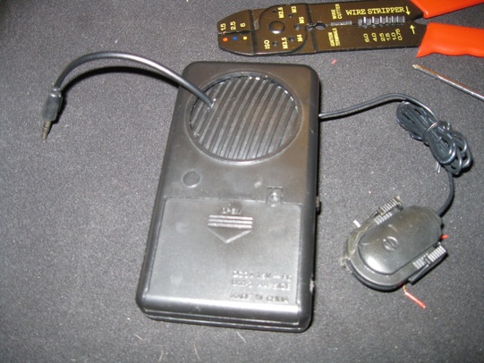
The first picture is of the device itself with the battery cover removed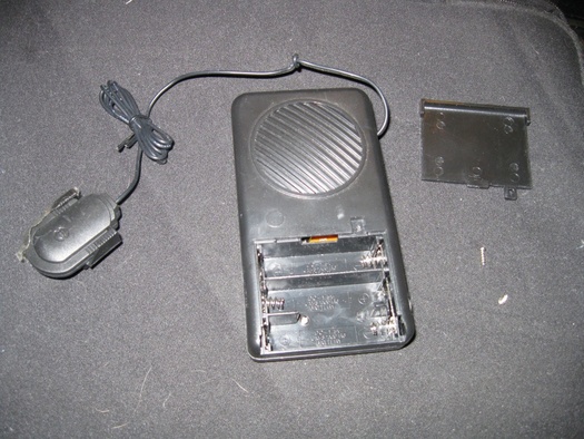
There are two screws on the inside of the battery cover that need to be removed
The screws on the back do not connect to anything that needs to be removed so it's best to leave them alone
Next we have a picture of the inside.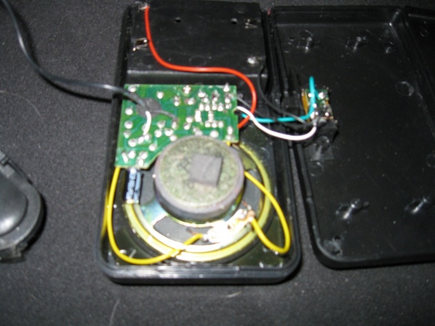
we are interested in the two yellow wires connecting to the speaker
Since I didn’t plan on using this as a stand-alone device in the future I removed the speaker. This is optional it will work fine with or without the speaker.
If you plan on removing the speaker cut the wires as close to the speaker as possible. NOTE DO NOT CUT BEFORE THE RESISTOR (The little brown thing with stripes on it) OR YOU COULD FRY YOUR MIC PORT ON YOUR COMPUTER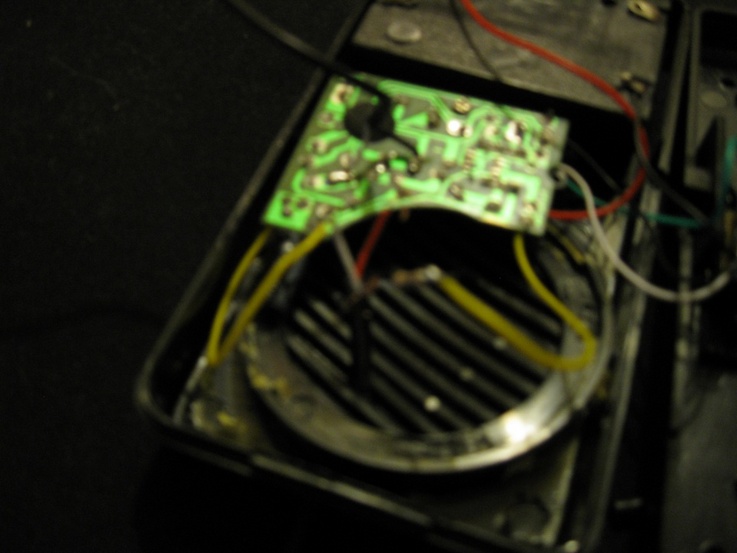
The next step is to attach your new audio out plug.
If you decided to leave the speaker attached you will need to make a hole for the wire to fit through. If you removed it stick a slotted screwdriver between the speaker cover and you should be able to pry them apart enough to slide the wire through.
Once you have the wire through remove the cladding to expose the interior wires. There will be three wires coming out of it one red, one black, and one either white or yellow.
The red and white/yellow wires are audio Right and Left. The Black wire is ground.
slide a piece of heat shrink over the two yellow wires coming from the voice changer (you can skip this step if you’re not removing the speaker)
connect the black wire to the resister and connect either the red or the white wire to the second one (it doesn’t matter which the audio is mono) you can cut the remaining third wire off.
At this point you can test the device with your computer to confirm its working. Once you confirm its working solder the wires together. Then slide the heat shrink over the exposed wires and the resister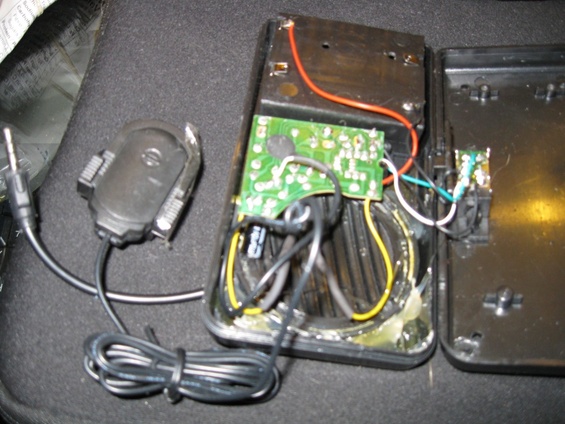
Your device should look like the one above
once your done test again then you can close it up